Horizontal measurements
Horizontal distances are distances laid on the ground or earth surface. We will discuss following topics in the chapter:
Rough distance measurement: pacing
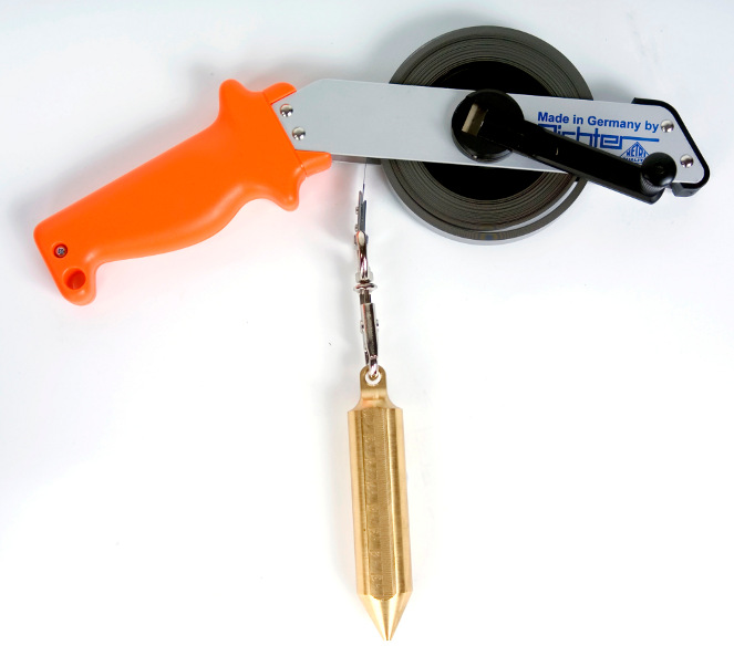
Rough distance measurement: Using a Measuring Wheel
Wheel tape does not provide high precision (which is around 1:200), but provides a convenient way to conduct fast measurement on a path or road including its curves.
Wheel typically has installed odometer to count the number of turns.
Using a tape
- Non metallic (e.g. fiberglass) tape can be used when only low accuracy
is required (around 1:1,000). Their usage is restrained to preliminary topo surveys.
- Steel tapes or tapes made from other metal alloys are intended to use
with accuracy of 1:5,000 or even 1:10,000. Such accuracy can be achieved when equipment is proper used by experienced crew.


A lot have to be done to conduct measurement in an appropriate way to obtain precision expected. To achieve a high level of accuracy one must avoid several potential random and systematic errors further explained.
Straight position of tape


If 1 m shift on distance of 100 m is not exceeded, then there are no needs to worry much about the error of the result.
There are tools available to check that tape (or its start and end point) is aligned into horizontal level. Such tool is, for example, "hand level", which has to be set up with the built-in spirit bubble.
Pulling with proper force
The tape has to be pulled with proper force, which is stated by the manufacturer.
Let us make an example, that instead of pulling by proper force of 20 N (2 kg) tape is pulled by 50 N. Let us assume, that cross section of tape is 10 × 0.5 mm (or 10×10-3 × 0.5×10-3 = 5×10⁻⁶ m2). From equations σ = P / A and σ = ε E arise that ε = P / AE. Module of elasticity E for steel is 210 GPa, therefore in our case ε = 30 / (5×10-6 × 210×109) = 3×10⁻⁵ or 1:35,000.
We may conclude that this issue is minuscule compared to others.
Temperature correction
For precise accuracies temperature correction needs to be done.
Let us make an example, instead of expected temperature of 20 °C it is 35 °C. Steel has a thermal expansion coefficient of 13×10-6 K-1. At 15 K diversion expansion will be 0.0002 or 1:5,000. The factor will be even more of interest if a survey is conducted in winter.
Wearing out the tape
Stations
Stations are temporary objects established to conduct measurement. They can be short-time lived, for purposes of measuring distances only, or long-time lived, based for further measurements.


- station (marks exact point of location) and
- guard (describes the location and helps to find a station).
Stations' marks
Marks on the ground must be made clear, visible and rigid. The marks are often established in order to conduct further measurements, e.g. using theodolite. In such cases their exact position will be found later using calculations. Marks will be established


- on pavement/road, or
- by a wooden stake in the ground.
Marks should be done by scratch, a color label can be used outside. Plumb bob is used over the tape against mark as explained on picture.
Electronic distance measurement (EDM)
EDM is designed to make a measurement of distances of up to tens of kilometers. There are two categories of inaccuracy with EDM:
- a) per measurement (usually ±1 mm to ±5 mm per measurement) and
- b) per distance (usually ±1 to ±5 parts per million).
Using EDM for short distances is not appropriate, not accurate, because the error is mostly fixed per measurement.
The early EDM instruments could measure long distances with an accuracy of about 5 parts per million (i.e. ±5 mm for every km or to ±150 mm over a 30 km line). Later versions are more accurate, usually able to measure with an accuracy of about ±2 parts per million (±2 mm per kilometre or ±60 mm over a 30 km line).
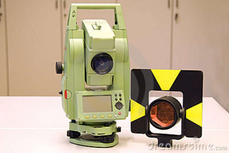
Nowadays there are also many types of accurate and compact EDM instruments integrated with an electronic theodolite and known generically as a Total Station. These instruments can also measure with an accuracy of about ±1 part per million, but are generally capable conduct a measurement only for shorter lines of about one kilometre.
Generally speaking, EDMI measures distances. Does not measure horizontal distance.


There are several types of instruments:
- instruments measuring distance only, using prism;
- instruments measuring distance, with no prism (just pointing to the destination object);
- modern equipment with built-in theodolite and computer.
Prism
Prism is equipment used together with EDM instrument. It serves to reflect back a signal (usually infrared light or microwaves 3 to 35 GHz) send by instrument. The larger prism is, the longer distances can be measured: multiplied prisms are being used for long distances.
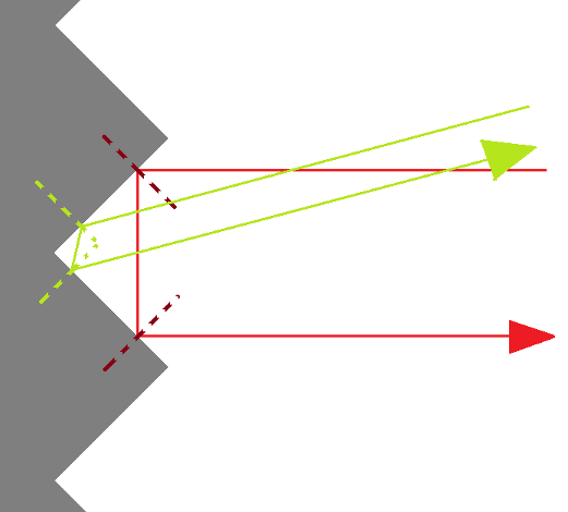
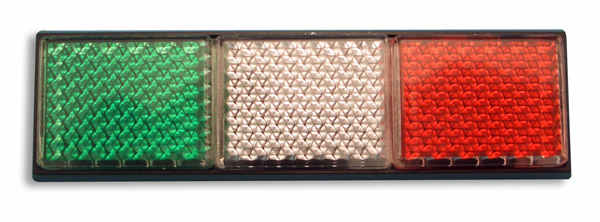
The magic behind prism is similar to that magic behind back reflectors used on cars.


Scheme above shows in 2D space two mirrors connected at the right angle. When beam reaches first mirror, it leaves the mirror under the same angle and continues to the second mirror where the same happens. If we study angles within the picture a little, we will see that the result is not depending on the angle of origin (within some borders): beam coming in leaves out to the direction of origin. Although the scheme is depicted for 2D space, in 3D space is happening analogy (for three mirrors, 90 ° between each other).
EDM predecessor
The unit on the picture is Geodimeter AGA NASM-2A from Sweden. In 1959, it was first commercially available electro-optical distance meter. Its total weight is near 100 kg. It is capable of measuring distances up to 50 km. The observations can be made in nights only.


